Personal quadruped · In progress · November 2026
Mini Bish Bot
I’m building a low-cost robot dog around custom cycloidal actuators and a printed leg mechanism. My work connects mechanical design, fabrication, wiring, and closed-loop motor control.
01 Mechanical design
From CAD
to a moving joint.
I designed the actuator around a 5010 motor, paired cycloidal discs, an output bearing, and printed housings. I’m refining bearing fits, disc flatness, stack clamping, and pin retention for smooth, backdrivable motion and repeatable assembly.
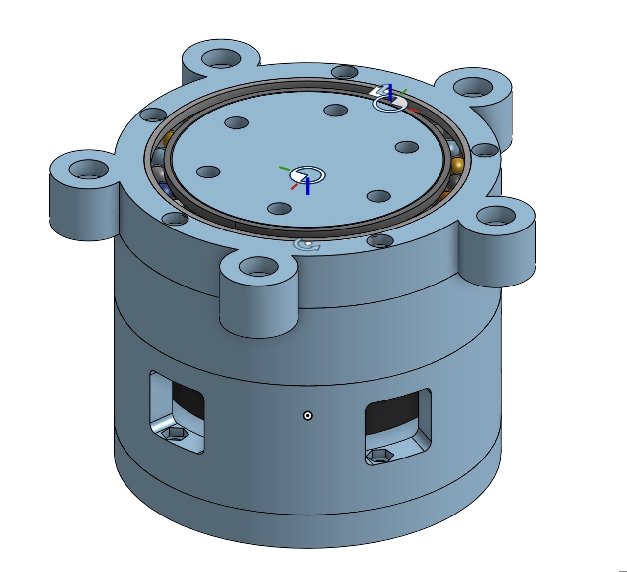
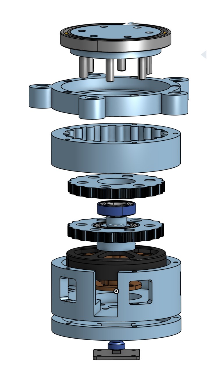
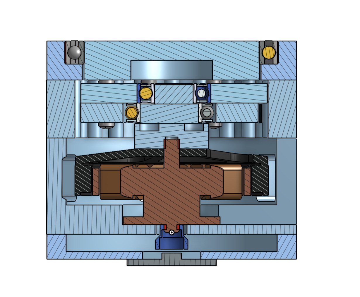
DFM drives the details: print orientation, part fit, fastener access, and assembly order. The goal is an affordable joint built from drone motors, printed parts, and inexpensive drivers.
02 Mechatronics
Command.
Measure. Refine.
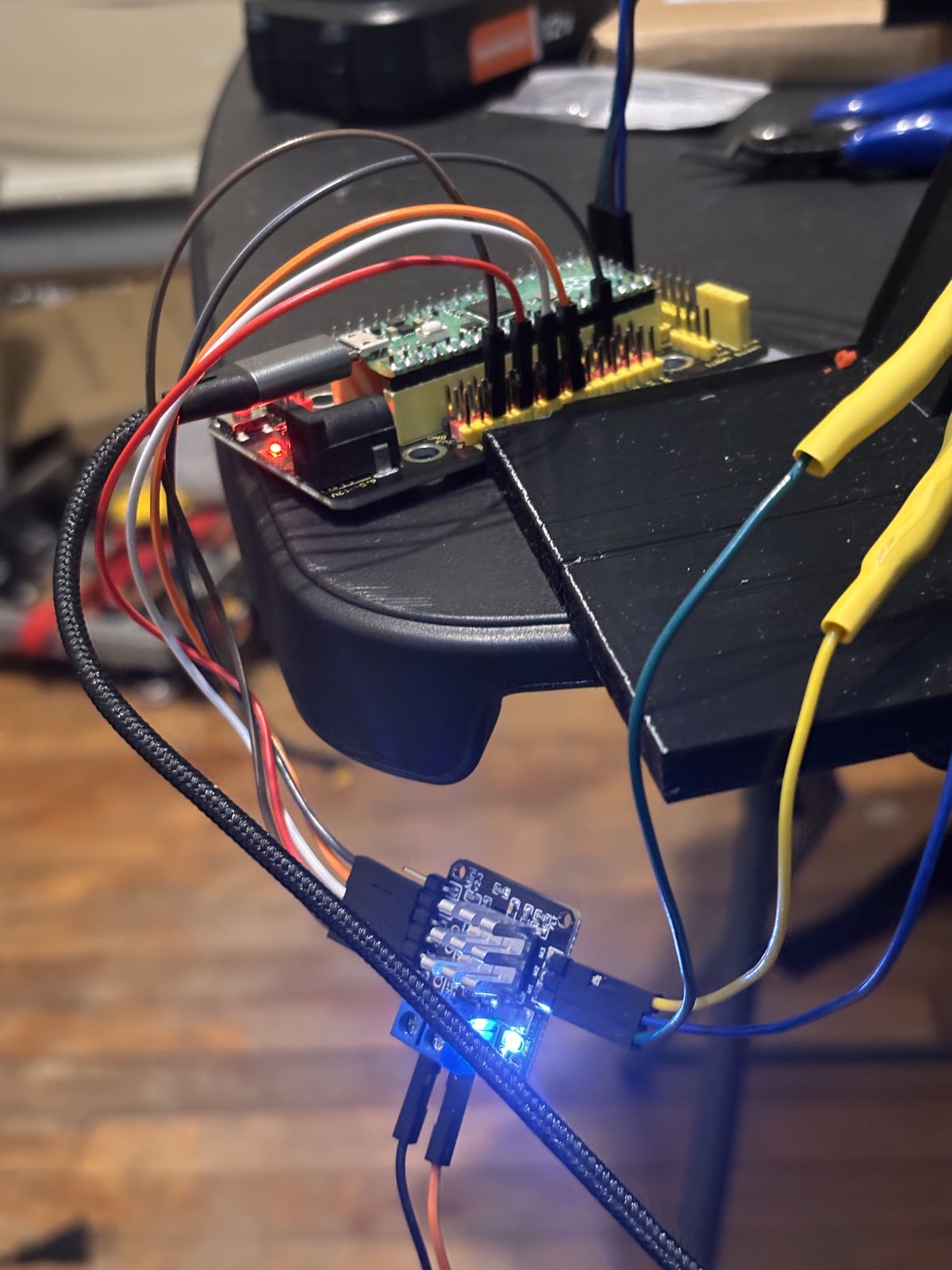
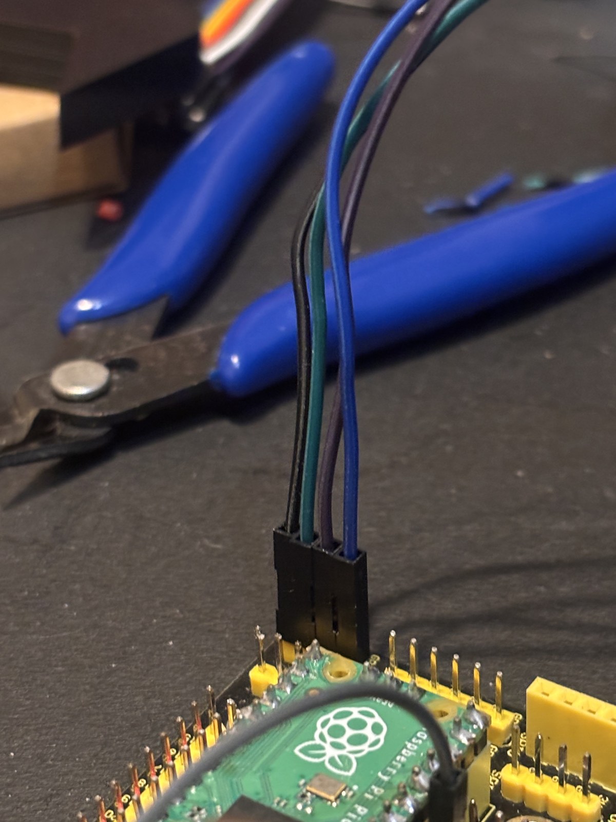
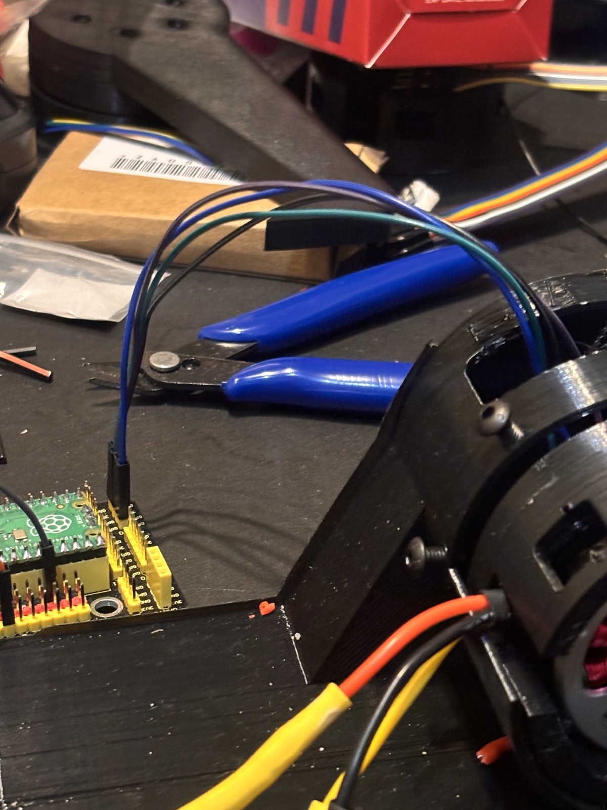
I’m developing position and velocity control with a Raspberry Pi Pico, MT6701 magnetic feedback, and SimpleFOC drivers. My Python interface runs motion sequences and logs encoder response and drive effort. Joint wiring and CAN bus integration connect this work to the full robot.
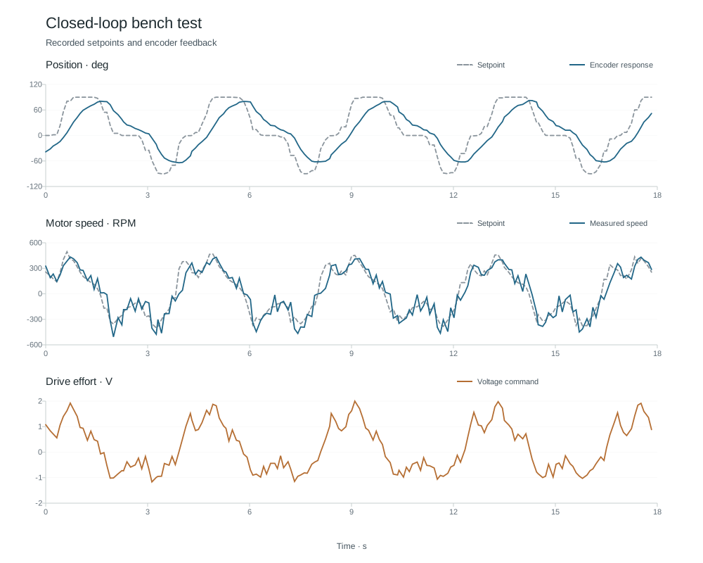
More bench footage & wiring
03 My leg mechanism
Four printed members.
Motors at the hip.
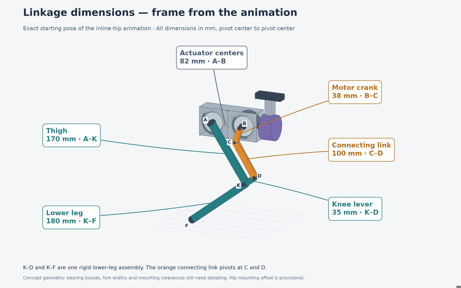
The latest design uses a thigh, a lower leg with an integral knee lever, a motor crank, and a 100 mm connecting link. Two leg actuators share a rotating box; an inline hip actuator swings the assembly sideways.
View the dimensioned linkage
Built through iteration.
I began by tearing down a robot from the previous year, then used that experience to develop my own actuators, printed parts, and joint interfaces.
Next
Loaded actuator and leg testing, full quadruped integration, and simulation-to-real locomotion work with NVIDIA Isaac Sim and Jetson Nano onboard compute.